Tolerances that actually fit: gaps, snap-fits and press-fits on FDM
The clearances we use every week for lids, hinges and press-fit pins — and why 0.2 mm is a starting point, not a law.
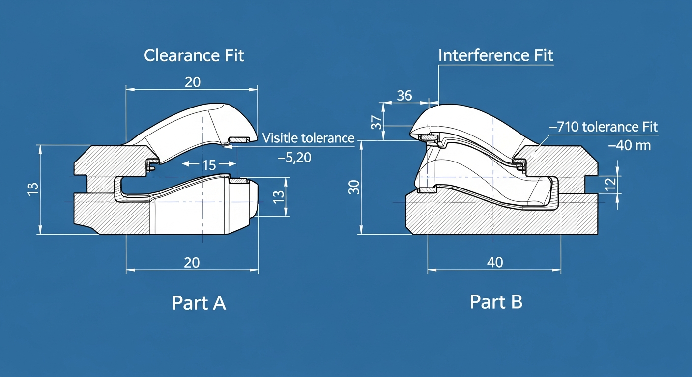
Most failed fits we see on the bench are not printer problems. They are design files drawn at nominal size, expecting plastic to behave like machined aluminum. FDM parts grow slightly at the outer walls and shrink on inner holes. Plan for it and you will get a part that clicks together the first time.
Starting clearances
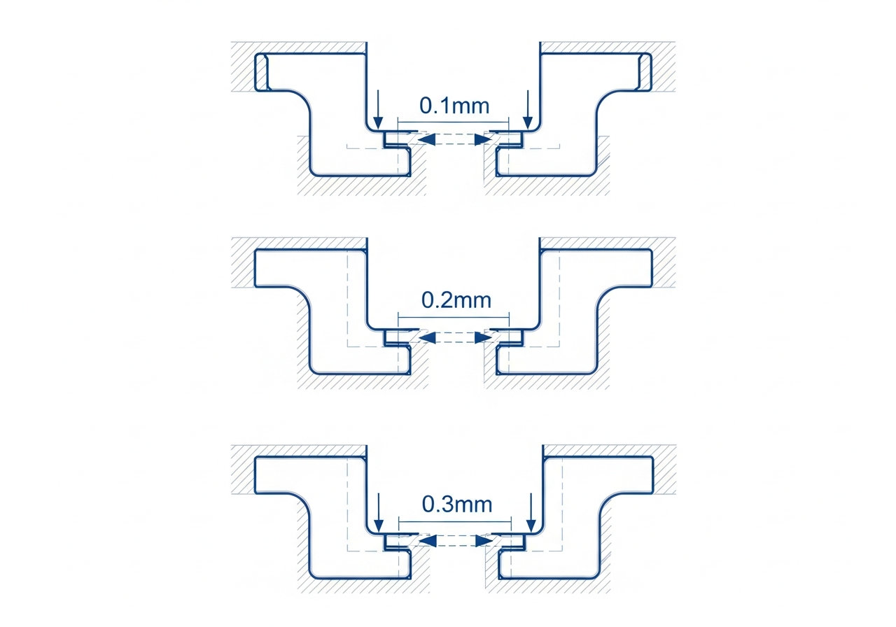
- Sliding fit (lids, drawers): 0.3–0.4 mm per side.
- Snug fit (removable caps): 0.2 mm per side.
- Press fit (pins, bearings): 0.05–0.1 mm interference, then test.
Snap-fits that survive
Give cantilever snaps a generous root radius and print them so the layers run along the arm, not across it. PETG forgives far more flex than PLA. If a snap is going to be opened more than a dozen times, tell us and we will orient it for strength.
Test coupons save money
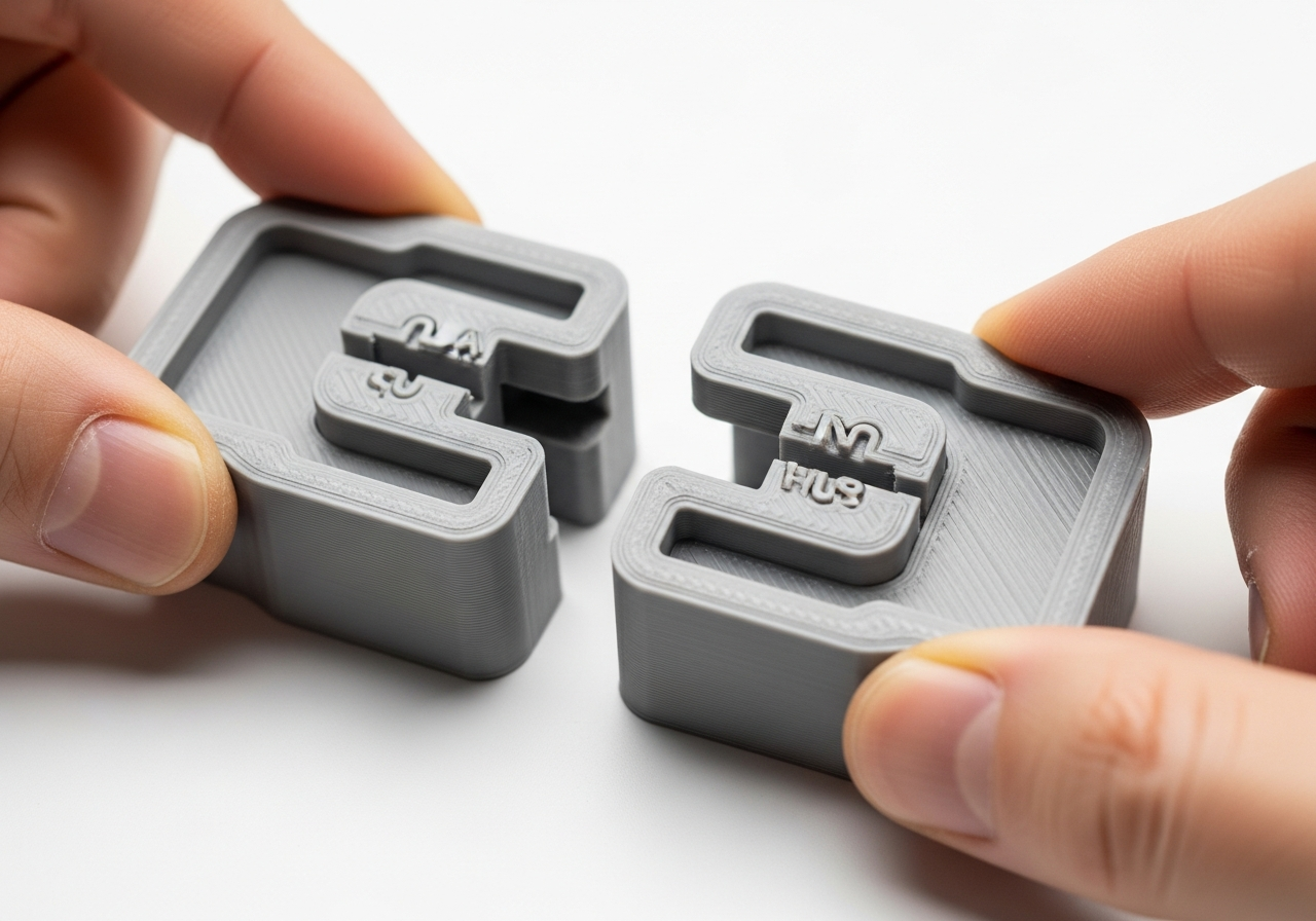
For anything with a critical fit, quote a small coupon with just the mating features first. It usually costs a few dollars and turns a three-revision project into a one-revision project.
Have a file this applies to?
Get an instant Austin quote